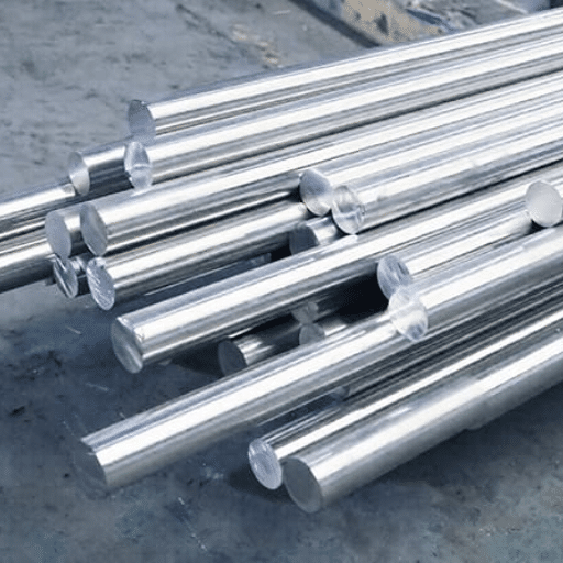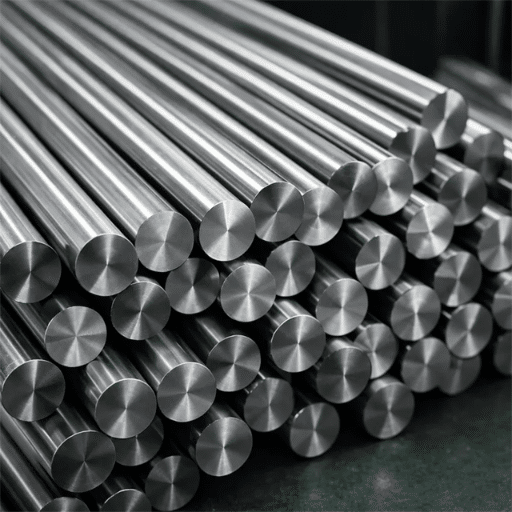
Machining 2205 duplex stainless steel needs rigid support, a sharp but strong edge, and cutting data for the actual tool and stock. Plan passes to cut beneath the work-hardened surface left by earlier cuts, within the tool’s and machine’s limits.
A copied speed leaves questions open. Was the part supported close to the cut? Was feed per revolution or per tooth? Did the data apply to a named producer’s improved-machinability product?
Check those details before copying the setup.
If tools wear out fast or finish varies, start with the setup record. This guide covers stock identity, turning, milling, drilling, wear checks and first-piece inspection. Use it to plan a trial you can assess.
Key Takeaways
- Confirm the stock designation, producer and delivered condition before selecting cutting data.
- Support both workpiece and tool near the cutting zone; preserve enough allowance for planned passes.
- Keep speed, feed units, tool class and coolant conditions together when reading a reference table.
- Diagnose the worn edge before changing settings; built-up edge and plastic deformation call for different responses.
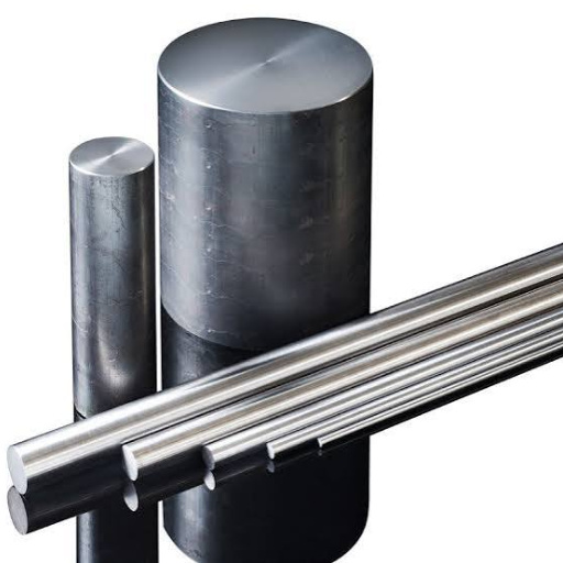
Start with the duplex stainless steel selection guide if material selection is still open. Compare stainless steel bar forms and prepare the required grade, condition and blank size before making a material inquiry.
What changes when machining 2205 duplex stainless steel
High starting strength and work hardening
2205 starts strong and work-hardens as it is cut. The International Molybdenum Association (IMOA) handbook says its initial work-hardening rate is at least comparable to common austenitic stainless steels. Its higher starting strength adds to the challenge. This doesn’t mean every previous pass leaves a layer of fixed hardness or depth.
Rubbing changes the surface the next pass will meet. IMOA advises planning cuts below the work-hardened layer. Check the previous cut, stock left and tool range together. A very light cleanup pass may leave the edge cutting within that affected surface.
Use the IMOA duplex fabrication handbook, chapter 11 for the underlying guidance on rigidity, sharp edges and pass sequencing. A blanket percentage reduction from a 316 program cannot account for those variables. Keep the operation and actual edge condition in view.
Confirm grade, product and supplied condition
The grade name defines material requirements, not the whole cutting setup. Check the material record: UNS grade, heat identity, form, producer and supplied condition. Keep that record with the setup sheet so the next operator knows which stock the data describe. The S31803 versus S32205 guide explains designation and purchase requirements without turning them into machining parameters.
Named products need care too. Alleima describes Sanmac 2205 as a machinability-improved material and gives data for specific tools. Those data describe that product and its stated conditions. They don’t prove that an unknown 2205 bar will cut the same way.
Illustrative scenario: A planner receives a quotation for generic 2205 bar, while an old setup sheet names Sanmac 2205. Before using its table, the planner needs to confirm the new stock’s identity and the tool assumptions. The shared grade family alone does not resolve that mismatch.
The Alleima Sanmac 2205 datasheet is useful for seeing that distinction. Treat a branded material recommendation as a bounded reference, then seek suitable data for the material actually ordered. If the record names only 2205, ask which producer and condition the quoted cutting data cover before approving the setup sheet.
Build a stable setup before choosing a faster tool
Hold the work and cutting edge close to support
Rigidity comes first. IMOA recommends keeping tool extension short, supporting the workpiece and balancing a sharp cutting edge with adequate edge strength. A sharper edge isn’t always stronger. A strong edge can still rub if its shape is wrong for the cut.
Select it with the tool supplier.
Review the load path from spindle to holder, insert, workpiece and fixture. Record these checks before choosing a faster tool:
| Setup item | What the record should show |
|---|---|
| Tool support | Holder, tool extension and overhang |
| Work support | Grip length, projection and support near the cut |
| Engagement | First entry, holes, cavities and uneven stock |
| Inspection | How the part is held during each check |
For a long bar, thin wall or interrupted cut, find what limits support before raising output. A new coating won’t fix a cutting zone that lacks support.
Blank preparation belongs in the same review. Note the sawn end, surface condition, available grip length and any holes or cavities that interrupt engagement. Select sawing conditions from the blade maker’s guidance for the actual section and material. Do not copy a tooth pitch or cutting rate from a different blank simply because both are duplex steel.
For a new setup, a short note can help more than another speed value. Does the first pass meet a solid surface, cross a hole or remove uneven stock? Include a simple sketch showing support locations and the intended cut. This gives the tool supplier something concrete to assess.
Plan roughing, allowance and first-piece checks
Plan roughing and finishing as a sequence. Leave enough stock for the intended finishing cut, considering the work-hardened surface from prior passes. Review depth, feed and edge geometry together rather than prescribing one minimum depth for all parts. Thin sections also need a plan for how clamping affects the dimensions being measured.
Illustrative scenario: A thin component meets a dimension while clamped but differs after release. The next decision is to compare clamped and free-state measurements, fixture loading and the removal sequence. That change alone doesn’t prove its cause or justify a heat treatment.
Agree how the part will be held when its size is checked against the drawing. Take readings between cuts where needed to find when it moves. Don’t set a fixed rest time after roughing without evidence for that process.
Keep heat treatment as a separate engineering choice. The IMOA handbook sets limits on heat treatment of duplex steel. It doesn’t support using a routine carbon-steel stress-relief cycle for this problem. Record the changes in size first; have any proposed heat treatment reviewed for the actual product and service.
2205 machining: choose tooling and operation-specific data
Turning: keep the cutting conditions together
Carbide is a common turning choice, but other tool materials can also cut 2205. Outokumpu includes high-speed steel (HSS) examples in its guidance. Tool class, edge geometry and setup determine which recommendation is relevant; “carbide” alone is not a complete tool specification.
The table below reproduces selected Outokumpu starting examples for its 2205 guideline. These examples aren’t a released program for an unknown part. Its turning feed is in millimetres per revolution; milling feed is in millimetres per tooth.
| Operation and tool class | Cutting speed | Paired feed or coolant condition |
|---|---|---|
| Carbide turning, finishing | 100 m/min | 0.1 mm/rev |
| Carbide turning, medium | 85 m/min | 0.4 mm/rev |
| Carbide milling, finishing | 90 m/min | 0.1 mm/tooth |
| Carbide drilling | 45 m/min | External coolant |
| Carbide drilling | 60 m/min | Internal coolant |
Source: Outokumpu 2205 Machining Guideline, page 1. Confirm the actual tool, depth, diameter, engagement and machine limits before using any example. The drilling rows do not supply a feed for an unspecified drill.
Illustrative calculation: For a 50 mm turning diameter and the medium-turning example of 85 m/min, spindle speed is n = 1000 × 85 / (π × 50), approximately 541 rpm. At its paired feed of 0.4 mm/rev, the calculated feed rate is approximately 216 mm/min. This converts the source values; it doesn’t prove they suit the part.
Do not average unrelated tables. IMOA Table 12 gives a different carbide face-turning roughing range: 90-120 m/min, 0.3-0.6 mm/rev and 2-5 mm depth. Its scope differs from the quick examples above. Check the type of cut and stated conditions before choosing a trial point.
Milling: manage engagement and coolant deliberately
Milling introduces repeated entry and exit. Outokumpu recommends short tools, good chip evacuation and attention to holes or cavities that interrupt the cut. Its curved-entry guidance addresses engagement damage. Check how the cutter enters the work.
Can chips clear without being cut again?
For milling, table feed equals feed per tooth × cutting teeth × spindle speed. For turning, feed rate equals feed per revolution × spindle speed. Don’t interchange the two feed units. Record cutter diameter, tooth count, radial engagement and axial depth with the selected speed.
Before the first cut, check the units on the setup sheet against the source row. Then agree which part features and wear observations will be checked. A correct RPM calculation settles the conversion only; it doesn’t release the cut for production. Keep the source row with the trial record so its conditions remain visible.
Coolant advice is operation-specific. IMOA’s carbide face-milling guidance recommends dry cutting, particularly for roughing, while its drilling guidance uses coolant. Use the method advised for the actual cutter and cut. Neither “always flood” nor “always dry” covers every duplex job.
Drilling and threading: check the method’s limits
For drilling, check the drill type, diameter, hole depth, point condition, coolant delivery and chip-removal method. Outokumpu distinguishes external and internal coolant examples and emphasizes stable support during breakthrough. A speed alone leaves gaps. You also need the drill’s feed and working limits.
For tapping, thread turning or thread milling, record thread form, size, depth and gauge needs. Ask the tooling supplier about the chosen method for the actual stock and equipment. A portable pipe threader cannot be approved or rejected solely from “2205”; torque, support, tooling and acceptance still need review.
Before extending a drilling or threading trial, record chip clearance, tool condition and the gauged result. Keep the first-piece checks tied to the drawing; an apparently clean thread alone doesn’t establish acceptance.
If a cutting problem prompts a material change, revisit 2205 versus 2507 selection. A different alloy requires application approval, not just a more convenient machining setup.
Diagnose tool wear and work hardening before changing settings
Read the edge before changing the program
Two damaged inserts can point toward different actions. Outokumpu’s troubleshooting guide distinguishes built-up edge, flank wear, notching, plastic deformation and long chips. Reducing speed may help one wear mode while making another worse. Examine the wear location and cutting conditions before choosing a response.
Use the following as a diagnostic starting point. These responses follow the producer’s wear guide. Check the wear mode and tool limits before a trial change.
| Observation | What to check | Producer-guided response to evaluate |
|---|---|---|
| Material adhering to the edge | Whether built-up edge is present; actual cutting speed | Assess a higher speed within the tool’s range |
| Wear on the flank | Edge condition and how wear progresses | Assess a lower speed for longer life |
| Local notch at the depth-of-cut line | Notch location and repeated cutting depth | Assess variable depth where geometry permits; review speed trade-offs |
| Edge deformation | Whether plastic deformation is present | Assess reduced speed and feed |
| Long, troublesome chips | Chip form, feed and chip-breaking geometry | Assess feed adjustment within the tool’s working range |
These are separate diagnostic paths, not instructions to change all settings at once. The guide notes that increasing speed can reduce notching while increasing flank wear. That trade-off is a reason to document the edge and part together, rather than choosing one number from a checklist.
Illustrative scenario: One trial leaves material attached to the edge; another leaves an edge that appears deformed. Calling both “poor tool life” hides the evidence needed to choose a response. Compare each observation with the producer’s wear descriptions before deciding whether speed should rise or fall.
Make the next trial interpretable
Record a baseline before changing the program:
- Stock identity, insert code and edge history.
- Operation, speed, feed, depth and coolant.
- Chip form and a clear image of the worn edge where possible.
- Part size and surface result, as well as time in cut.
Those fields link the edge observation to the actual cut. Keep failed trials too, so a later setup doesn’t repeat an unexplained change.
For the next trial, change one factor where practical and record the rest. Sometimes a new tool shape also needs new cutting data. If so, record both changes. The next person needs to know which setup produced the result.
Set tool-change limits around the drawing and how wear grows. A handbook’s tool-life plot describes its test, not a promised change interval for your job. Review the trial record with the tool supplier before extending the cut or releasing a larger batch.
Turn the machining trial into a useful material and inspection handoff
Match the stock record to the process record
A useful trial record lets someone else identify the stock, repeat the setup and see how the result was judged. Check three things on their own: stock compliance, whether the setup can cut the part, and whether the finished part passes. A stock certificate doesn’t prove the fixture and cutting sequence will meet the drawing.
Use a compact handoff with the following fields:
- Material: specified grade, producer or product identity, heat reference, supplied condition and required documentation.
- Blank: form, starting dimensions, allowance, quantity and relevant surface condition.
- Setup: machine, fixture, support, tool and holder codes, overhang and interruptions.
- Cut: operation sequence, speed, feed with units, depth, engagement and coolant method.
- Acceptance: drawing revision, dimensions, inspection condition, surface requirements and recorded findings.
Turn each gap into a question. Ask the material source about an unclear supplied condition. Ask the tool supplier for a missing drill feed. If the part moves after release, review how it was held, cut and measured with the engineer in charge.
Keep finish, cleanliness and service approval separate
A bright surface doesn’t prove corrosion performance. Follow the required cleaning, handling and inspection plan. The IMOA handbook covers surface cleaning and inspection apart from cutting data. There is no single roughness limit in this guide for every 2205 job.
Likewise, successful machining does not authorize a material substitution. The 904L versus 2205 service-selection guide addresses a different decision: whether the alloy suits the operating environment. Keep that approval separate from the shop’s ability to produce the shape.
Return to the thin-part scenario: record the clamped and free-state readings, which operation preceded each reading, and the remaining acceptance question. That gives the next review a defined problem. It does not claim that waiting, reclamping or heat treatment has solved it.
Before requesting material, assemble the grade, product form, supplied condition, dimensions and allowance, quantity and documentation needs. That supports a clearer discussion of the blank without assuming available stock, machining capacity or a promised delivery date.
Machining 2205: common questions and next steps
Why is 2205 difficult to machine?
2205 brings high starting strength and work hardening to the cutting operation. Rigidity, edge condition and pass depth therefore matter alongside speed. IMOA recommends a sharp but adequately strong edge and a sequence that cuts below the work-hardened surface. A single machinability rating cannot describe every operation and setup.
Can HSS tools be used on 2205?
Yes. Outokumpu includes HSS starting examples, and IMOA guides HSS twist drilling. Carbide can support higher turning speeds, but it needs suitable rigidity and tooling conditions. Choose from data for the actual operation, tool and stock rather than treating carbide as a mandatory material requirement.
What cutting speed should I start with?
Start with the tool supplier’s recommendation for your operation, tool geometry, engagement and supplied material. Producer tables provide useful reference points when their conditions match. Preserve the paired feed and its units, convert speed using the relevant diameter, then assess a controlled first cut against defined acceptance requirements.
Should duplex 2205 milling be wet or dry?
Use the actual cutter maker’s recommendation for the engagement and tool grade. IMOA specifically recommends dry carbide face milling, especially for roughing; drilling guidance uses coolant. Those statements cover different operations. Record the selected coolant strategy and delivery method so a later trial can be compared on the same basis.
Can a portable pipe threader replace a CNC setup?
The grade name alone cannot settle that choice. Review the thread geometry, equipment torque and rigidity, suitable cutting tools, coolant access and required gauges. Seek equipment and tooling guidance for the actual job. A successful cut on another material or thread does not establish acceptance for the proposed 2205 part.
For machining 2205 duplex stainless steel, the next useful step is a complete material and setup record. Review the site’s stainless steel bar information and prepare your grade, condition, drawing dimensions, allowance and quantity for a focused material inquiry.