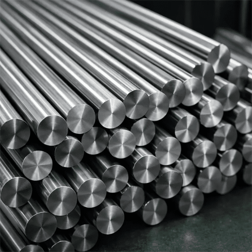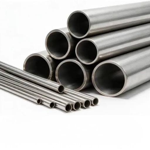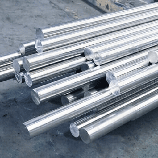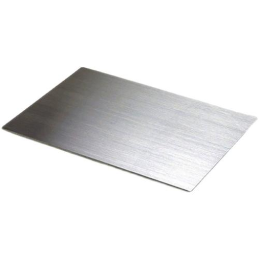
Forming duplex stainless steel starts with the grade, supplied condition and forming method. Match the setup to those inputs, then check the part after unloading. For 2205 sheet and plate, plan the inside radius, equipment load and springback compensation together before cutting the production blank.
A press can reach its programmed position while the released flange misses the drawing. If you are transferring an austenitic stainless design to duplex, that gap deserves attention before material is cut. This guide connects producer guidance with a practical trial record, so you can identify missing inputs and discuss them with the forming shop.
For a material inquiry, review our stainless steel sheet product information. Prepare the grade, delivered condition, thickness and drawing before using its quote control.
Key Takeaways
- Confirm the exact material and product condition before choosing bend guidance.
- Read inside-radius ratios with their producer and process scope attached.
- Measure unloaded geometry before fixing compensation or the flat pattern.
- Treat any heating proposal as a complete thermal-route decision.
- Agree finished-part dimensions, surface requirements and inspection records before production.
What changes when forming duplex stainless steel
Confirm grade, form and delivered condition
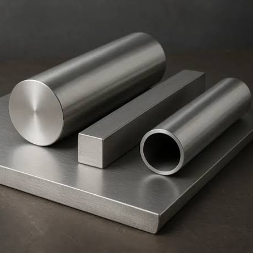
The name 2205 does not describe the whole forming job. Record the specified designation, product form, thickness and delivered condition against the drawing. If designation wording differs between the order and certificate, resolve it before selecting process data. Our guide to S31803 and S32205 designations explains that material-identity question.
Duplex stainless steels combine relatively high strength with lower ductility than common austenitic grades. More force is needed to produce permanent deformation, and springback changes the unloaded shape. These principles are discussed in the IMOA duplex fabrication handbook, third edition, 2014. They explain why a familiar 316L setup needs review; they do not provide a machine-specific tonnage calculation.
Cold work also raises strength as forming proceeds. This work hardening matters when a part needs several forming operations: later steps act on material that has already changed. Discuss the full sequence with the shop, including whether severe forming needs an approved intermediate solution treatment.
Keep tensile elongation separate from a permitted bend strain. A certificate’s elongation result comes from a defined tensile test. It cannot, by itself, approve the local deformation around a bend or establish the final part’s fitness for service. The forming procedure and applicable specification still matter.
Match the forming mode to equipment and ductility
A straight press-brake bend, a rolled cylinder and a deeply formed head need different tooling and assessments. For sheet forming, distinguish drawing, where material feeds into the tool, from stretching, where local thinning is important. A producer’s discussion of drawing performance does not automatically establish the stretching limit for your part.
Check equipment and tooling capacity for the actual grade, bend length and method. Avoid converting a broad strength comparison into a press setting. The shop must consider the load path and its equipment limits as well as the drawing’s radius.
Illustrative scenario 1: A planner changes an austenitic bracket drawing to 2205 while retaining the old bend note. Before ordering the blank, the shop asks for the delivered condition, rolling direction and proposed tooling. The useful next step is to close those information gaps. No successful bend or approved tolerance is assumed in this example.
For the wider material-selection context, use our duplex stainless steel selection guide. Keep the grade decision connected to the forming plan without treating a general grade overview as process approval.
Plan the bend radius, tooling and blank together
Read radius guidance with its conditions
For flat stock, define inside bend radius as Ri and material thickness as t. The ratio Ri/t describes the inside radius relative to thickness. It does not identify the die opening, punch radius or finished angle. A tube drawing may instead specify a centreline bend radius, so confirm the convention before comparing values.
Outokumpu’s forming guidance gives a minimum inside-radius-to-thickness ratio of 2 for duplex bending guidance. Use that producer guidance as a scoped starting point for flat-product planning. The actual grade, condition, geometry and tooling still need review; a ratio alone does not approve the component.
Continuing the illustrative bracket example, assume t is 6 mm and Ri is 12 mm. Dividing 12 by 6 gives Ri/t = 2. This arithmetic describes the assumed drawing. It does not establish a safe punch, die, load or forming sequence, and it does not predict the unloaded radius.
Check tooling, flange access and edge preparation
Review the bend with the tooling arrangement visible. In particular, check whether the required overbend is physically possible once earlier flanges have been formed. A drawing can show the finished shape without revealing interference during the process. The same review should include support for the workpiece and protection of the required surface.
| Planning input | What to record or ask | Decision it supports |
|---|---|---|
| Material identity | Grade, thickness and supplied condition | Which producer guidance applies |
| Bend geometry | Inside radius, bend length, angle convention and tolerances | Tooling and capacity review |
| Tool arrangement | Punch, die opening, tool ratings and flange access | Whether the proposed method is feasible |
| Blank orientation | Rolling direction and bend-line orientation | A representative trial and repeat setup |
| Edge and surface condition | Cut-edge preparation, burr removal and permitted marking | Crack and surface inspection planning |
| Forming sequence | Order of bends, handling and overbend clearance | Access to each bend through completion |
Clean tooling, suitable lubrication and controlled handling belong in this discussion. Outokumpu addresses friction and tooling as forming variables. Specify the surface that matters to the finished part, then ask how the shop will protect it. Do not assume that an acceptable angle also establishes acceptable surface condition.
Give the fabricator finished dimensions and a trial blank
Keep the finished drawing and proposed blank size separate. Specify dimensions after unloading and name the faces or edges used as measurement references, called datums.
The blank is the flat piece cut before forming. Its size is a process input. Clear flange dimensions help the shop tell an angle error from an error in the flat pattern.
Request a representative trial using the intended stock condition and tooling. Agree what will be recorded before the trial begins. If the shop proposes a different radius or sequence, return that change to the drawing owner for review rather than silently changing the finished requirement. Keep the approved drawing revision attached to the trial record so later comparisons use the same geometry.
Measure springback before fixing the production setup
Record loaded and unloaded geometry consistently
Springback is the elastic recovery that occurs when forming load is removed. Duplex’s higher strength makes this an important setup variable. A comparison chart for one specimen and bend arrangement cannot provide a universal correction angle for every thickness or tool combination.
Start with a representative coupon or trial part and define the angle convention. Some records describe the included angle; others describe the amount of bending from flat. Without that definition, two correct measurements can appear to disagree. Identify the measurement faces, instrument and unloaded measurement point as part of the record.
The following is a proposed trial-record structure, rather than a mandatory acceptance standard. Adapt it to the actual equipment and project requirements.
- Record stock identity, measured thickness, supplied condition and orientation of the bend line.
- Record machine and tool identifiers, die opening, intended radius, method and forming sequence.
- Record the commanded setting and, where safely measurable, the loaded geometry without bypassing machine safeguards.
- After unloading, measure the angle, inside radius and critical flange dimensions using the agreed convention.
- Document the adjustment, repeat the check and retain the accepted setup with the drawing revision.
Calibrate bend allowance and compensation on the actual setup
Compensation addresses the difference between the formed setting and the required unloaded shape. Bend allowance addresses the material length used in the curved region when developing the blank. Adjusting one does not automatically solve the other. A flange-length mismatch may remain even after the angle has been corrected.
Change a defined setting deliberately, then compare the next part with the same measurement method. Record what changed so the result can be interpreted. Avoid changing the blank, tooling and compensation together without a record; that makes it hard to identify which change affected the result.
Illustrative scenario 2: A closed box looks correct in CAD, but its final flange leaves too little clearance for the proposed overbend. The planner and shop compare the bend sequence, tool access and unloaded dimensions before revising the flat pattern. This example identifies a planning conflict; it reports no actual production result.
Recheck after material, tool or sequence changes
A saved setup should state the conditions under which it was established. Review its applicability when the grade, thickness, delivered condition, tooling or sequence changes. A successful trial on convenient scrap is weak evidence if the production stock has different relevant characteristics.
Grade substitution also needs a fresh review. Our 2205 versus 2507 selection comparison provides the broader selection context. It cannot authorise carrying the same forming settings between the grades.
Keep the first-piece record with the job, including any deviations and their approval. Ask the fabricator to return the unloaded measurements with its proposed setup.
Agree who may release production after reviewing that record. If a trial misses the drawing, keep the issue open. Correct the setup or obtain the drawing owner’s approval for a change. The record should show what was measured and why the part was accepted.
Choose cold, warm, or hot forming from a supported route
Keep the cold-deformation statement within its product scope
Whether a cold-formed part needs subsequent heat treatment depends on more than whether it bent without visible cracking. Product guidance, deformation, service conditions and specification requirements all affect the decision. Geometric success alone does not establish the finished material condition.
For example, Alleima’s SAF 2205 seamless tube and pipe datasheet permits cold bending to 25% deformation without further heat treatment. It also lists exceptions linked to service conditions and specifications.
This advice applies to that producer’s tube and pipe. It does not set an allowable deformation for all 2205 plate. Read the stated exceptions before applying it to a particular service.
Before using a percentage, establish how deformation is defined for the product and operation. Do not substitute certificate tensile elongation or an unrelated sheet-metal calculation. If the project requires a specified final condition, the process must deliver that condition even when the dimensional trial is satisfactory.
Read producer thermal ranges separately
The same Alleima bending section gives a hot-bending range of 1100–950 °C and states that hot bending should be followed by solution annealing. Keep the product scope and follow-up attached to the range. The temperatures alone do not define a complete heating, holding, cooling or acceptance procedure.
Flat-product guidance must come from the applicable flat-product source. Do not combine the lowest temperature in one producer’s document with the highest in another to create an apparently wider working window. Ask the responsible process engineer to identify the source and explain its applicability to the stock being formed.
| Proposed route | Question to settle before work | Follow-up to define |
|---|---|---|
| Cold forming | Is the geometry feasible within the applicable product and project requirements? | Dimensional trial and final-condition requirements |
| Warm forming | What approved route controls the thermal exposure? | Required treatment and acceptance evidence |
| Hot forming | Which grade-specific producer guidance applies? | Solution treatment, cooling and final inspection route |
Plan the final condition and acceptance before applying heat
IMOA’s handbook discusses thermal exposure risks and the need for appropriate solution treatment. Do not treat local heating or routine low-temperature stress relief as an automatic way to recover formability. Uncontrolled exposure can introduce metallurgical problems that an angle measurement cannot reveal.
Before agreeing to a heated route, identify who approves the procedure and who accepts the finished condition. Define the treatment and inspection records that the order requires. Keep welding and full heat-treatment qualification in their dedicated procedures; the forming plan should identify those dependencies rather than replace them with a short temperature note.
Turn forming limits into an inspection and supplier handoff
Agree the inspection questions
The finished angle is one item in the release record. Check the inside radius and critical dimensions against the agreed drawing datums. Include cracks, edge condition, visible surface damage and permitted tool marking in the discussion. Agree the method and acceptance basis before the first production part is formed.
Visual checks cannot establish every property needed for service. Where the specification requires further examination or testing, identify its method, acceptance criteria and responsible party. Avoid adding an arbitrary hardness, phase-balance or corrosion-test limit simply because it appears in another project’s paperwork. The governing requirements must determine the inspection scope.
Separate the stock supplier’s responsibilities from the fabricator’s. A material certificate records the supplied stock against its stated requirements. The finished part also needs the agreed dimension and fabrication records.
Decide how each blank will stay linked to its stock record after cutting. If the stock changes, update that link and review the forming plan before releasing the part. Keep rejected trial pieces separate from accepted production parts in the job record.
Keep the material and fabrication records connected
Illustrative scenario 3: Two quotations describe a bent component, but one assumes a cold-formed final condition while the other includes thermal treatment. The buyer asks each supplier to state its process assumptions, final condition and inspection scope. The quotations cannot be compared on price alone until those differences are understood.
Use a drawing-led inquiry checklist:
- Drawing number and revision, quantity, finished dimensions, datums and tolerances.
- Grade designation, thickness, product form and required supplied condition.
- Bend radii, angle convention, orientation constraints and proposed sequence.
- Required finish, surface protection and permitted marking.
- Applicable specification, final condition and inspection records.
- Trial approval responsibility and treatment of deviations or substitutions.
State which details are fixed requirements and which are proposals for the shop to review. That distinction helps the supplier identify a genuine process conflict without guessing whether it may change the design. Carry agreed changes back into the controlled drawing and order before production release.
Forming duplex stainless steel questions and next steps
What bend radius should I specify for 2205?
Define the inside radius and thickness, then consult guidance for the actual product and supplied condition. Outokumpu gives a duplex inside-radius-to-thickness ratio of at least 2 as forming guidance. Treat it as a starting point for process review, with tooling, geometry and an unloaded trial still requiring confirmation.
How much springback should I allow?
There is no single compensation angle for all duplex bends. Use a representative trial with the intended tooling and a clearly defined angle convention. Measure the unloaded shape, adjust the setup and record the accepted conditions. Keep those results separate from generic comparison charts or settings established for another material.
Does every cold bend require annealing?
No universal answer applies across all products and service conditions. Alleima’s named SAF 2205 tube and pipe guidance permits some cold bending without subsequent treatment, subject to exceptions. It does not establish a plate allowance. Use the applicable specification and producer advice to define the required final condition before fabrication.
Can I heat duplex locally to make it easier to bend?
Do not turn an improvised heating step into the forming procedure. Duplex thermal exposure requires control because unsuitable conditions can impair material properties. Have the responsible engineer define the complete route, including any subsequent treatment and acceptance checks. A part that reaches the right angle still needs its required final condition.
Can a CAD K-factor replace a trial bend?
A K-factor helps calculate bend allowance for a flat pattern. It does not independently establish springback compensation, tool access or the finished dimensions on your setup. Use representative measurements to check the bend model and retain the accepted inputs. Review them when material, tooling, thickness or the forming sequence changes.
The bracket, box and quotation examples share a practical lesson: identify the missing input before changing the setup or approving the order. A useful forming plan joins material identity, finished geometry, trial measurements and final-condition requirements in one reviewable record. It also names who can approve a change when the proposed process cannot meet the drawing.
Ready to prepare the material inquiry? Review our sheet product information and quote entry, then provide the drawing revision, grade, condition, dimensions, quantity and required records. Ask the intended fabricator to confirm the forming route against those requirements.